Injection Moulding — Ejector Pin Inspection System
Injection Moulding — Ejector Pin Inspection System
Enhanced Process Backup Control System
A leading automotive parts supplier of injected moulded parts required a more robust solution to the existing injection press limit switches.
The Injection Press cycle involves four major steps:
- The closing, or clamping of the tool;
- Injecting the molten material;
- Cooling and solidifying of the material;
- Opening the tool and ejecting the newly formed piece.
During this final step, the new piece is pushed off the surface of the tool face by ejector pins and lifting shoes. After the robotic arm removes the piece, the ejector pins retract to begin the cycle again.
On occasion, the limit switches associated with these ejector pins fail, allowing the possibility of extended ejector pins at the end of the press cycle. The ejector pins and/or lifting shoes cannot be more than 2 mm off the surface of the tool after they have been retracted, or they will damage the grained surfaced of the tool, causing press downtime and significant repair costs.
As a preventative measure to avoid this potential damage to the Injection Press, JNE Automation‘s project team was tasked with developing an enhanced process backup control system. JNE provided application development, product procurement, assembly and installation, as well as services for project management, commissioning and training.

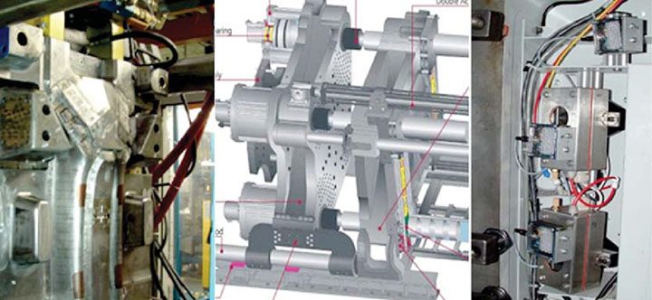
Injection Press schematic and operating equipment.
The press tool surface was divided into four visual inspection zones. Four DVT 510 Legend Cameras, each with a 16 mm lens, were individually enclosed in air purged NEMA 4X enclosures with 6 LED IRDA lights.
The trigger for the cameras to inspect the mould was driven from the Injection Press control system. This trigger would initiate the process of capturing the images of the tool surface, and with the use of DVT soft sensors, inspect those images for surface anomalies, i.e. protruding ejector pins. In the event the ejector pins were flush with the surface of the tool, the vision system would return an “inspection passed” signal back to the press and the moulding process would continue. In the event the vision system detected anomalies on the tool surface, an “inspection failed” signal would inhibit the press from continuing the cycle and notify the operations staff.
The system data was made available to management at their networked workstations, enabling the system to be monitored and controlled remotely. The successful completion of the project ensured the client would immediately be notified of any issues with the Injection Press, minimizing press downtime and eliminating significant repair costs.
Contact Us


