Typical Utility Station Details and Design
Typical Utility Station Details and Design
Keywords
Share
Summary
Utilities in a process plant are services which are not integral to the process, however, are still essential to plant operation.
Examples of utilities and their uses include compressed air for pneumatic power tools, nitrogen for purging instrument lines and water for cleaning. Utility headers are typically supported on pipe racks that extend the length of the plant. At locations where these utilities are required, branches drop from the header to where they can be accessed by operations and maintenance personnel. Multiple service drops are sometimes grouped together in centralized sites known as utility stations.
Utility piping systems have three parts:
- Point of production or source (red)
- Distribution piping (yellow)
- End users (green)
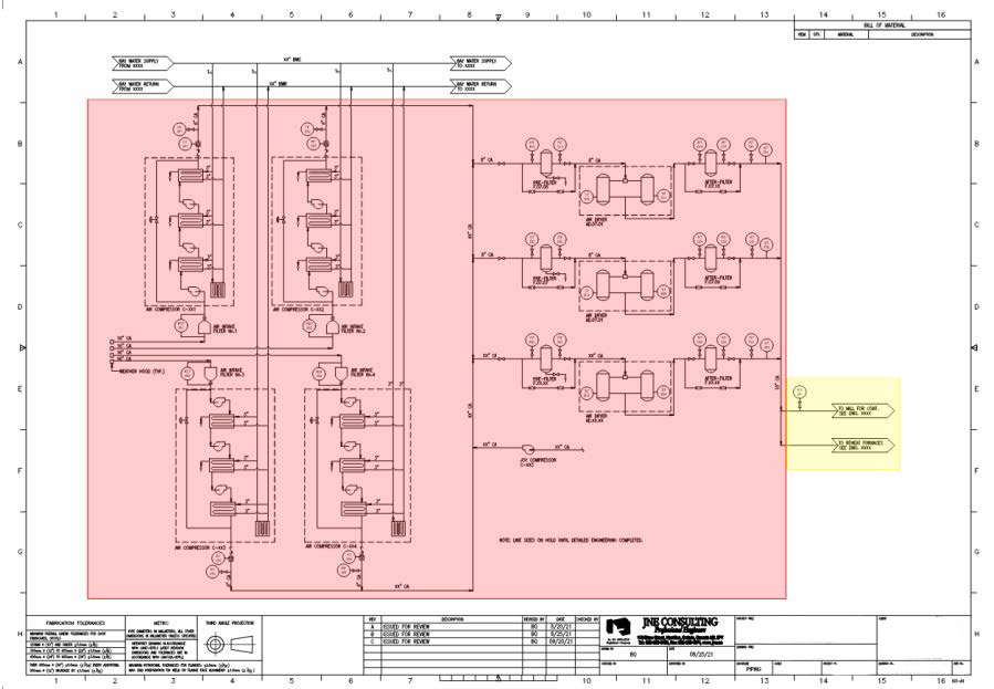
Figure 1: Compressed air PFD showing point of production and distribution piping.
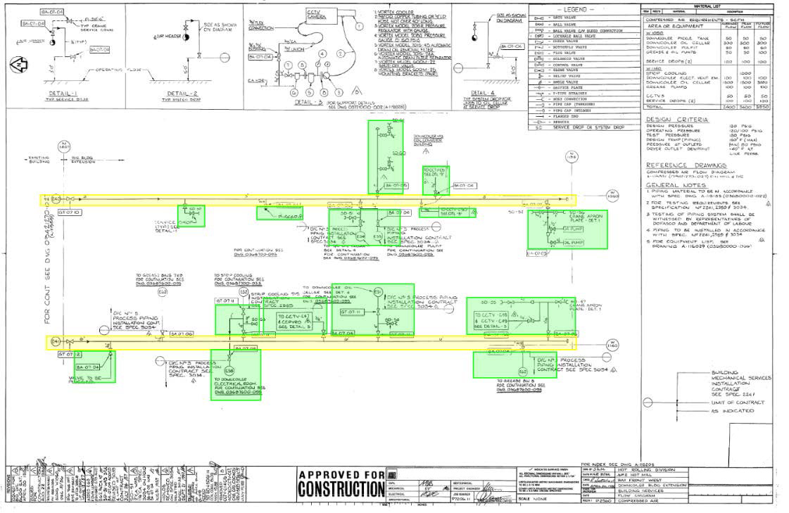
Figure 2: Compressed air PFD showing distribution piping and end users.
Distribution piping is typically supported on pipe racks. Generally utility piping is kept on the upper deck and process lines on lower levels. See below for a cross section of a typical pipe rack.
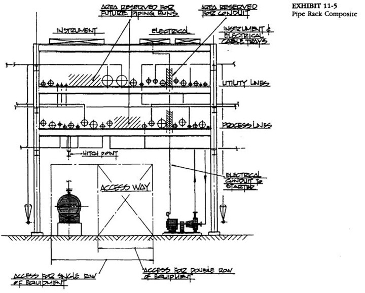
Figure 3: Compressed air PFD showing distribution piping and end users.
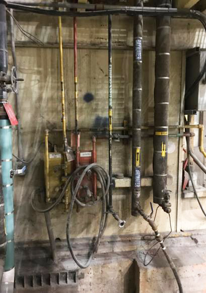
Figure 4 + 5: Typical utility station arrangement.
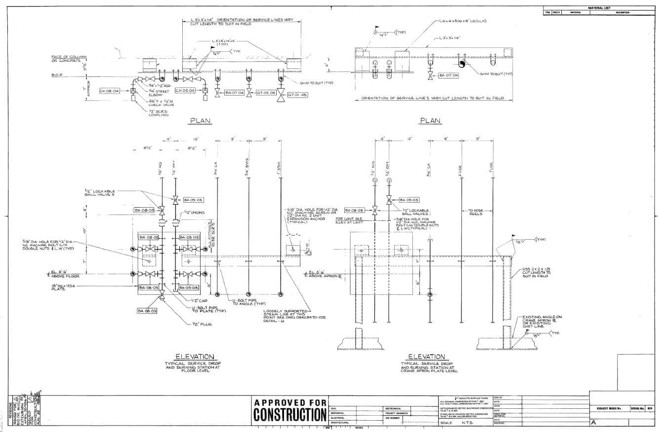
Figure 6: Typical utility station detail.
Codes and Standards
Project/Case Example
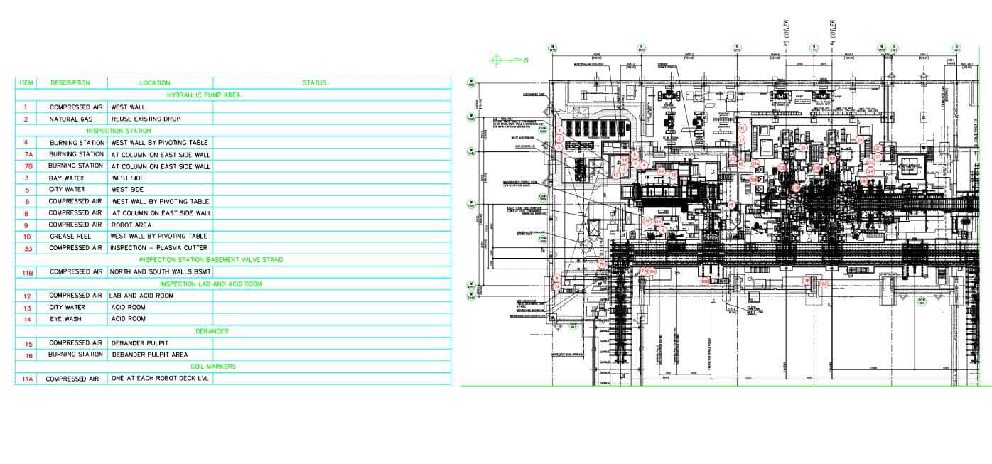
Project Objective: Design service drops to provide services to locations where required.
Design Inputs:
- Plant layout drawings / 3D Navisworks model / Single line schematics of services
- Client piping specification
- Client typical service drop drawings
General Procedure:
- Identify tie-in points on headers in pipe rack
- Locate wall/column to support vertical piping
- Confirm service drop would be accessible at that location
Solution/Best Practice
Considerations in designing utility stations:
- Access to station by plant personnel.
- Coverage radius of utility station (typically 15m radius).
- Walls/columns to support vertical piping.
- Flow of traffic (people, forklifts, cranes etc.) in proximity to the utility station.
- Valves and instruments should be placed in a way that they can be operated or viewed but do not impede access at grade and elevated walkways.
- Clearance should be provided to equipment that require in-place servicing or require removal from their fixed operating location.
- Requirement for hose connections