Oxygen system velocity
and material requirements
Oxygen system velocity and material requirements
Published October 2024
Keywords
Share
References
Summary
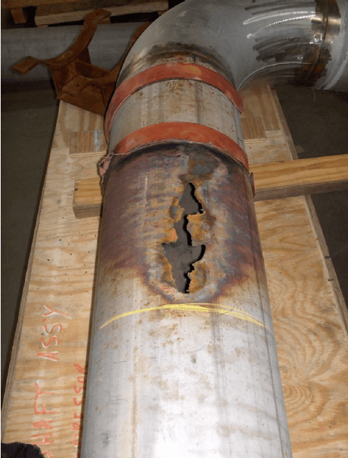
The intent of this knowledge file is to study the velocity limitation and material selection considerations in an oxygen system as per CGA G-4.4 code for oxygen piping systems to mitigate the risk of oxygen fires/explosions (as seen in Figure 1 below).
Figure 1: Stainless steel pipe oxygen fire.
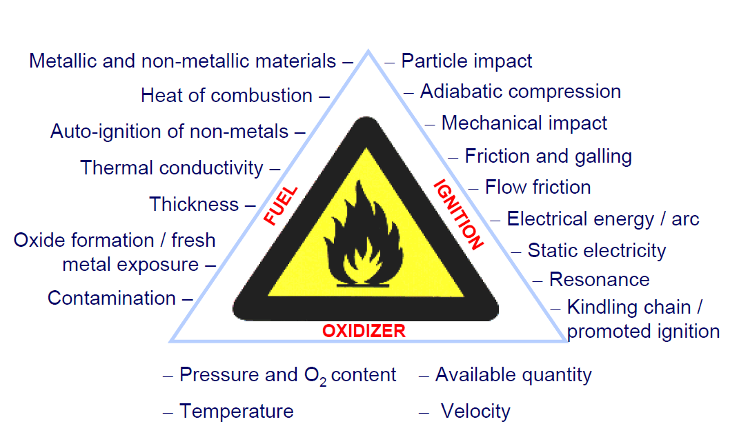
The fire occurs when 3 main elements such as an oxidizer, a fuel and an ignition source are present. Eliminating or minimizing one of the elements, decreases risk of fire, example:
Oxidizer is Oxygen. Reduce oxygen design pressure, temperature, concentration, and flows. Most of the time, the design parameters are given, and changes are not desirable or practical.
Fuel is material of pipe construction, or any contaminants in the pipe, such as particulates, corrosion, oil, greases. Check material compatibility (flammability and auto-ignition), select burn-resistant piping material for your oxygen system conditions. Ensure proper pipe cleaning.
Ignition source is any factors that can trigger the ignitions, such as high gas velocities and impingement sites that contribute to particle impact ignition, frictional heating or rapid-opening components such as valves that can produce adiabatic compression heating, static charge, lightning, etc.
See below for the practical design considerations for oxygen piping.
Design Consideration
- Velocity limitation
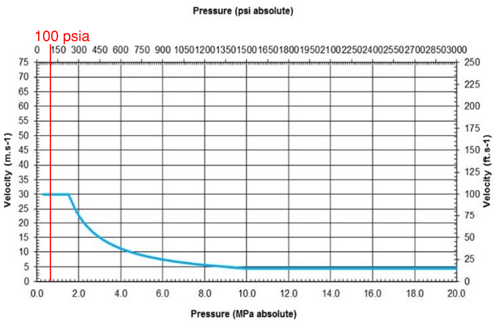
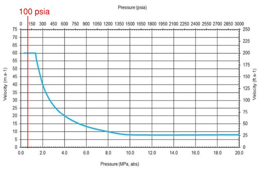
Oxygen velocity and impingement sites can contribute to triggering ignition through particle impact ignition. As such, CGA G-4.4 code specifies the maximum allowable oxygen velocity based on the design pressure for impingement and non-impingement sites (see Figures 2 & 3).
-
- High velocities can occur as a result of reducing pressure across a system component or during a system start-up where pressure is being established through a valve.
- Even small pressure differentials across components can generate gas velocities in excess of those recommended for various metals. For example, rapidly pressurizing a system from 0 to 100 psig will result in a temperature of ~ 500 F.
- Example of components with inherently high fluid velocities are:
- Pressure regulators, control valves and restricting orifices.
This video is an example of a flex hose liner material auto igniting when subject to high velocities:
- Impingement Sites
Impingement is the section of piping when the flow direction changes abruptly, or presence of eddies (swirling effect) leads to impact of particles with the system walls that can lead to gas impinging and cause a particle impact ignition.
The following locations are examples of impingement sites:
-
- Both butt weld and socket weld tees and socket weld elbows;
- Branch connections such as fabricated branches, weldolets, sockolets, and threadolets;
- Face of multi-hole diffusers and surrounding body;
- Short-radius elbows (radius of curvature less than 1.5 diameter);
- Socket-weld and threaded reducers;
- Reducers (eccentric and concentric) with greater than 3 to 1 inlet to outlet reduction section ratio (for flow from large to small);
- Mitered elbows (mitered cut angle greater than 20 degrees), and;
- Piping downstream of a pressure letdown valve up to a length of 8 pipe diameters (pipe diameters can be based on valve outlet size).
- Valves, conical strainers and Y strainers, filters, orifice plates, noise reduction devices, etc.
Refer to Figure 2 below for velocity limitations for impingement sites.
Figure 2: Velocity Curve in Impingement Sites.
- Non-Impingement Sites
The following locations are examples of non-impingement sites:
-
- Straight piping runs;
- Butt-weld tees with long (or smooth) crotch radius for flow from main to branch;
- Long radius diameter elbows (equal to or greater than 1.5 diameter);
- 90 degree mitered elbows made of 6 pieces (5 welds) as well as 45 degree mitered elbows made of 3 pieces (2 welds), providing that all internal surfaces are ground smooth; and
- Eccentric and concentric reducers with a maximum 3 to 1 reduction ratio.
Refer to Figure 3 below for velocity limitations for non-impingement sites.
Figure 3: Velocity Curve in Non-Impingement Sites.
- Exemption Pressure, material composition and thickness
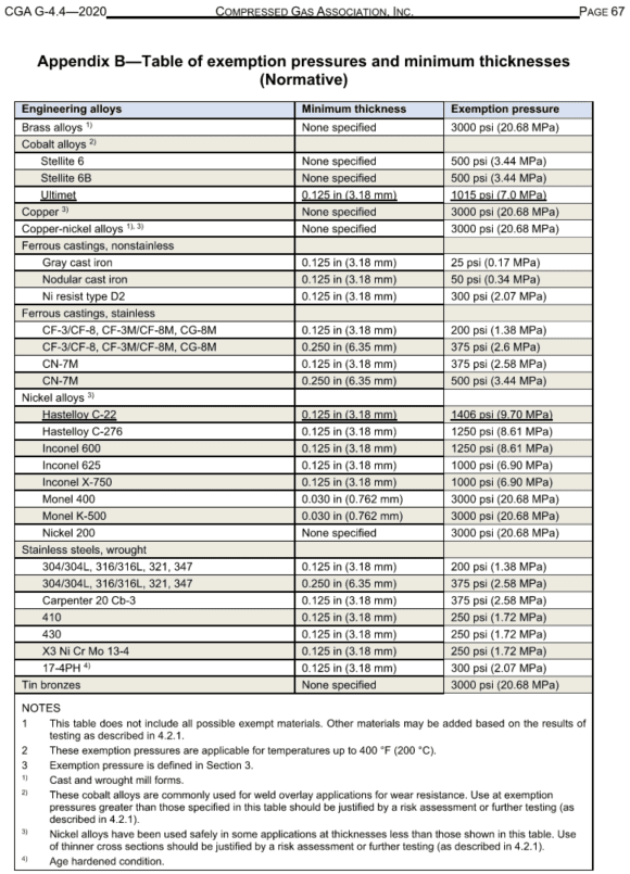
The code CGA 4-4 Appendix B (Figure 4) lists the basic compositions of the engineering alloys, the exemption pressures for the alloys and minimum required thickness for the materials.
The exemption pressure is the maximum pressure at which a material is not subject to velocity limitations in oxygen line, where particle impingement may occur. At pressures below the exemption pressure, ignition and burn propagation is unlikely to occur.
Thickness of the material is critical to determine the flammability of the component. If the thickness is less than recommended minimum, the alloy is considered flammable and velocity limitations for the system pressure shall be observed.
If the design pressure is less than the exemption pressure for a given material thickness specified in Figure 4, that oxygen system is exempt from the velocity restrictions.
Figure 4: CGA G-4.4 Appendix B – Steel Except Pressures and Thicknesses.
Project/Case Example
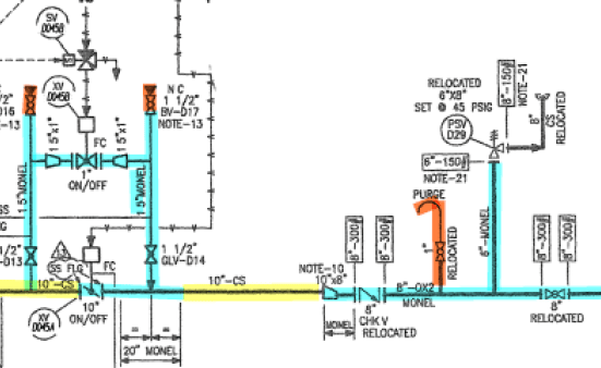
Project Objective: the client requested that JNE perform a study for the existing oxygen system after an increase of oxygen flow to ensure that the design complies with CGA G-4.4 code.
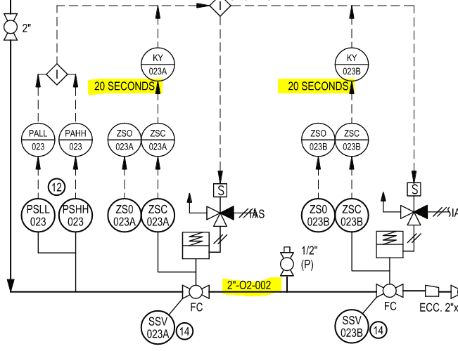
Figure 5: Example of Oxygen P&ID
The oxygen flow increase in existing 10” Carbon steel pipeline led to the gas velocities increase. JNE created a flow model to determine acceptable velocities along existing pipeline at impingement points. The components, where new velocities exceeded the limitations (based on Fig.2 above), were replaced with the exempt materials.
Some components, such as 10” ON/OFF automatic valve, were not replaced, though it is impingement area and velocity at the valve was higher than recommended. The existing automatic valve material of construction was Monel, which is “exempt material” at 3000 PSIG ” (see Fig.4, table B above), and velocity limitation DO NOT apply.
Solution/Best Practice
- Identify the design parameters (design flow, design pressure, piping and component material).
- Define components in the system that are impingement and non-impingement sites as per sections 2 & 3 above.
- Model the system in AFT Arrow to calculate velocities through the system.
- Compare calculated velocities to the impingement and non-impingement Figures 2 & 3.
- If system velocity is above curve in Figures 2 & 3, system redesign is required:
- Reduction of velocity by increasing line or component(valve) size.
- Change to exempt material based on Figure 4 pressure and thickness requirements.
- Consider system start-up (filling up line from 0 psig) scenarios and how to mitigate high velocities:
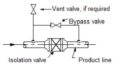
- With the use of a small size bypass/pressurization valve around the main line valve (bypass line/valve will require Exempt Materials) as seen in Figure 6 below. Recommended bypass lines based on the main header line size can be seen in Table 1 below.
Figure 6: Limiting velocity through a bypass pressurization line.
| Main Line Size | Bypass Valve Size |
|---|---|
| <4″ | 3/4″ |
| 4″ | 1″ |
| 6″–8″ | 1 1/4″ |
| > 8″ | 1 1/2″ |
Table 1: Pressurization and main line sizes.
NOTES:
-
- The by-pass valve is used for initial pressurization only and to be locked closed after pressurization. If the oxygen system has pressure relief valve (PRV) downstream of by-pass line, ensure the PRV is sized for the larger flow: either in main line or by-pass line.
- If the pressure drop across the main line valve on start-up is more than 1% of the upstream pressure, an equalization bypass valve is required regardless of using non-except and except materials to avoid adiabatic compression. Equalization valve to be locked closed after start-up.
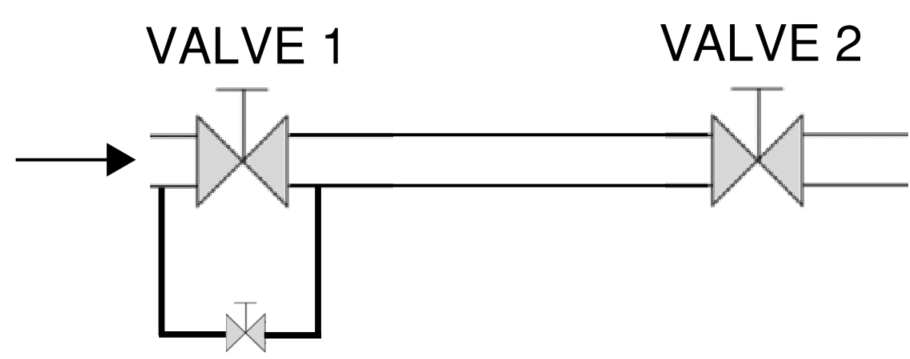
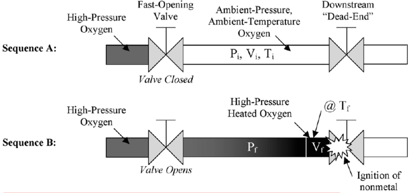
Create an SOP (with client’s approval) that is developed and is utilized to open large valves in series prior to pressurization of the line. For example, open Valve 2 prior to pressurizing through the bypass around Valve 1 as seen in Figure 7 below.
It will help to avoid adiabatic compression and ignition seen in Figure 8.
Figure 7: Sequence of opening large valves in series to eliminate bypass valve requirements for Valve 2.
Figure 8: Adiabatic compression leading to ignition of a non-metallic valve seat.
- Install slow opening/closing shut-off valves:
- Eliminate impingement sites through design where possible such as follows:
-
- Use long radius diameter elbows instead of short-radius elbows;
- Use reducers with less than 3 to 1 inlet to outlet reduction;
- Use butt-weld tees with long (or smooth) crotch radius for flow from main to branch instead of both butt weld and socket weld tees and socket weld elbows.


