Gravity Flow Piping Design
Gravity Flow Piping Design
Published June 2026
Keywords
Share
Summary
Gravity drainage systems occur frequently on industrial plants.
Typical examples are:
- The condensate take-off from a condenser.
- The liquid take-off from the base of an absorption column.
- The emergency overflow from an atmospheric pressure storage tank.
Whenever liquid flows by gravity out of a vessel or down a pipe there is a potential problem of entrainment of gas by the liquid. Entrained gas not only raises the pressure drop but also reduces the static head available to drive the flow and overcome the created pressure drop. These effects can reduce the flowrate drastically below the design value.
Entrained gas can give rise to unsteady flow conditions like surging which, in extreme cases, can result in equipment failure. Figure 1 shows a typical sequence which may occur for an absorption column with an undersized liquid outlet.
When the liquid level in the tank is low enough, the liquid entrains gas (Figure 1a). The resulting increase in pressure drop and reduction of head restrict the flow rate, and the liquid level rises (Figure 1b). Eventually, the level rises enoughto stop entrainment (Figure 1c). However, gas still in the outlet pipe causes the level to continue to rise until the gas is all swept out (Figure 1d). Now, the outlet pipe is running full flow (as was assumed in the design), but the static head, becoming higher than was assumed, creates excessive flow, which causes the level to fall until entrainment occurs again and the cycle is repeated (Figure 1e).

There are three approaches for the design of gravity drainage systems:
- For flooded flow, with the outlet piping size based on single-phase criteria.
- For self-venting flow, with the liquid velocity in the outlet pipe kept low enough to allow gas to flow counter-currently to the liquid.
- For acceptable entrainment, but with the system designed to accommodate it.
This knowledge file will focus on designing for self-venting flow.

Project Example
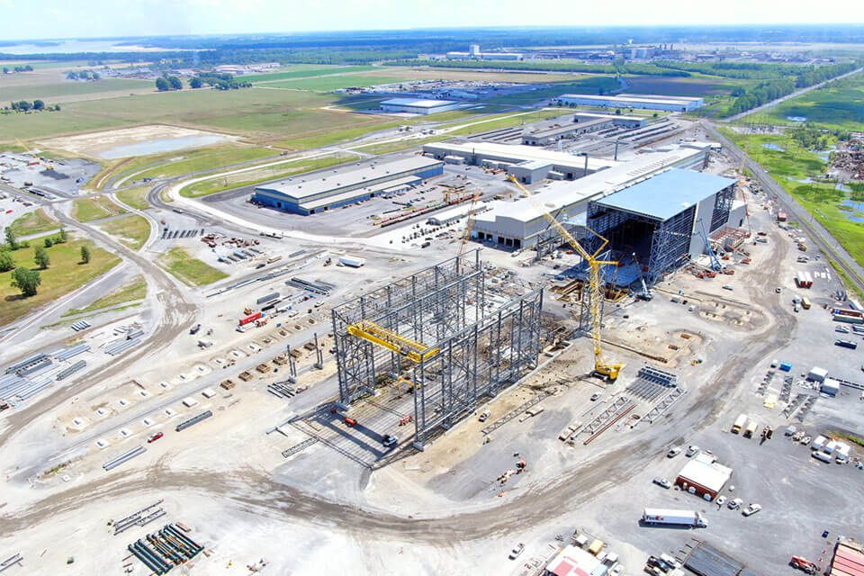
JNE has conducted gravity flow piping design on many projects. In the case study of a large rail mill, the drain lines for the electric arc furnace (EAF) spray cooled shell design were improved, as the site had difficulty with water drainage via gravity for self-venting flow. This project resulted in two possible solutions being to increase the drain header size or change drain elevation.
Codes and Standards
While the methods used in this knowledge file are engineering best practice rather than a code, related design work should comply with:
Company or client piping specifications for general piping requirements should be used in accordance with the above applicable codes.
Solution/Best Practice
Company or client piping specifications for general piping requirements should be used in accordance with the above applicable codes.

Where,
J*L = Dimensionless superficial volumetric flux (Froude number)
QL = Volumetric flowrate
d = Pipe inner diameter
g = Gravitational acceleration
Bottom of Vessel
A slug of gas will be entrained in a liquid flowing down a vertical pipe if the value of J*L > 0.3. For values of J*L less than this, the gas slug will rise against the liquid flow. This forms the basis of the design method for self-venting flow which is that J*L < 0.3.
The Froude number is defined as the ratio of the surface wave speed to the actual liquid velocity. It can be calculated using the equation below:

Side of Vessel
With a value of J*L < 0.3 the pipe entrance will be less than half full and the liquid level in the stagnant region away from the overflow will be less than 80% of the pipe diameter above the bottom of the pipe (Figure 4).

If a pipeline is to run only partially full from the side of a vessel, it must be inclined to provide the static head to overcome friction losses. A minimum slope of 1:40 is recommended as a rule of thumb. To avoid having the liquid carrying gas forward, adequate free area must be left in the pipe to allow gas to pass backward.
- For pipes ≤ 8”, liquid depths should not be more than 1/2 the pipe diameter.
- For pipes > 8”, liquid depths up to 3/4 of the pipe diameter may be possible.
An important assumption to make is that flow in a partially filled pipe is uniform. This means the liquid depth is treated as constant. Inside the pipe, the friction is balanced by the potential energy changes due to the inclination of the pipe. Insuch a case, the mean velocity is related to the inclination and the depth of the flowing liquid. From this assumption the mean velocity can be calculated to determine the appropriate size for established flow.

Where,
VL = Mean velocity
m = Hydraulic Mean Depth
ε = Pipe inner diameter
v = Kinematic Viscosity
It is important to note that sizes calculated from the Froude numbers take-off branch will be more conservate than sizes calculated from the mean velocity equation for established flow.
The initial velocity in the outlet line designed to run half full is less than the equilibrium velocity in a pipe having a slope of 1:40. In the real world, as the liquid accelerates down the pipe, the liquid depth diminishes with distance to that of the depth corresponding to the established flow at a given flowrate. To validate the assumption of constant relative depth reducing the pipe diameter stepwise is recommended.
For long lengths of pipes, the following design approach is suggested:
- Size the take-off branch of the side of the vessel for J*L ≤ 0.3. If this is a non-standard pipe size choose the next standard size above the calculated value. Continue this size for at least ten pipe diameters.
- Determine the pipe diameter corresponding to ½ or ¾ full established flow for the required flowrate. Again, select the nearest standard size above the calculated value. It is important to remember that the flow value calculated from the mean velocity equation represents the maximum flow for the selected size and fill that will sufficiently provide self-venting flow.
- Reduce the pipe size from the take-off size to the established size using an eccentric reducer such that there is no change in the slope of the bottom of the pipe. The reducer should have a minimum length of twice the upstream diameter.

If this procedure is followed for pipes of slope 1:40, the liquid depth straight after the reducer will not exceed 75% of the reduced pipe diameter.
For long inclined pipes it may be worth considering a second reduction down to the size corresponding to an established flow relative depth of 0.75. This reduction ca1n take place after a further fifty diameters.
It is important to try and not incorporate bends in this piping system because these might cause entrainment or surging.
Bends in the horizontal plane are not expected to cause problems provided the slope of 1:40 is continued around the bend and the bend is gentle. Recommended radius of 5 times the diameter.

In the vertical plane, the number of bends should be reduced as far as possible. Vertical sections should be replaced by gently sloping sections if possible.
Vertical pipework, including bends from or to vertical sections, should be sized for J*L ≤ 0.3. Long inclined pipes can be sized for ½ or ¾ full established flow but should be increased back to the full diameter for flooded flow before any vertical piping sections. Changes in diameter should be by eccentric reducers of length equal to twice the larger diameter and arranged such that the bottom of the reducer has a slope equal to that of the pipework on either side.